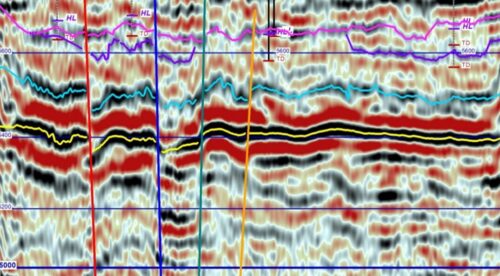
Seismic reflection can be used for mapping subsurface voids, sinkholes, abandoned mines, and other cavities. The survey can be done using either a shear wave source or a conventional compressional wave seismic source. Seismic reflection provides high-resolution data compared to other geophysical methods, making it a valuable tool. The method is best suited for investigation depths greater than 10 to 20 m, depending on the geology. For more shallow investigations, other geophysical methods such as seismic refraction, multi-channel analysis of surface waves (MASW), electrical resistivity imaging, ground penetrating radar, or gravity may be better suited.
Data Acquisition
For shallow investigations, sledgehammers may be used as a seismic source. For deeper investigations, more powerful sources such as accelerated weight drops or explosives should be used. A line of geophones is placed on the ground surface and a seismic source is then engaged at regular intervals along the geophone spread. The resulting reflections are recorded by the geophones and stored in a seismic recorder. Seismic reflection surveys require that the geophone and shot spacing be appropriate for the particular application. The number of channels should be chosen so that the spread length is appropriate for the desired depth of investigation, and the geophone spacing needs to be such that the rugosity of reflecting surfaces is imaged properly.
Data Processing
Data processing is the same as for any other seismic reflection survey. Seismic reflection data is initially recorded in two-way travel time, i.e. the time it takes for a wave to travel to a reflector and return. To be useful for engineering, these times must be converted to actual depths using velocity models derived from velocity analysis or calibration with boreholes. If digital geophysical sonic and density (gamma-gamma or compensated) borehole logs are available, a synthetic seismograph may be generated to compare with and significantly improve the depth calibration of the imaged seismic data.
Data Interpretation
Reflection surveys are usually interpreted using seismic cross-sections showing distance along the line against two-way travel time or depth. The cross-section should provide a view of the seismic stratigraphy, both vertically and laterally. Naturally occurring subsurface voiding is often caused by dissolution of evaporite and carbonate rocks. These dissolution voids are typically filled with rubble, air, fluid or any combination causing anomalous chaotic features in seismic records. Identifying areas with subsidence and associated void also relies on mapping diffractions, scatter, and sagging or bowl-shaped structures. Manmade cavities from mining and other activities involving removing rock mass, may have similar signatures as dissolution voids, especially if partially backfilled or collapsed. Intact mine work may have a more distinct signature.
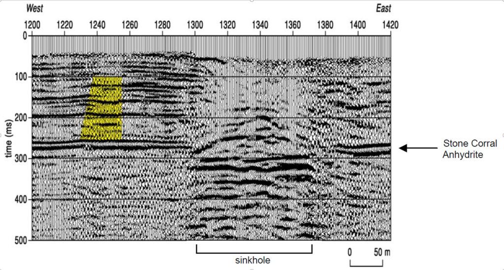
The figure below presents a seismic reflection cross-section showing the response over a sinkhole feature. The sinkhole is caused by dissolution of the Hutchingson Salt Formation below the Stone Corral Anhydrite Formation. It causes an offset in the Stone Corral Anhydrite due to upwards void migration, and an abrupt change in the reflection pattern in the overlying sandstone from stratified to chaotic due to segregated rock. The highlighted area shows signs of sagging and bowl-shaped stratigraphy, indicating loss of material.
Deliverables
The report will primarily focus on discussing the findings on the survey, and interpretation of the various seismic sections. Borehole data (if available) should be used to correlate the seismic cross-sections. Descriptions of equipment and software used, test setup, procedures, data acquisition details, and data processing schemes should also be discussed.
Advantages
The seismic reflection method provides a pictorial section that resembles the subsurface layers. The method is not restricted, as is the seismic refraction method, to a section in which the layer velocities successively increase.
Limitations
The method is best suited for investigation depths greater than 10 to 20 m, depending on the geology. The seismic reflection method is one of the more expensive geophysical methods, and requires a significant amount of knowledge to process the data. In addition, any local vibrational noise will reduce the signal-to-noise ratio and make the resulting seismic section less definitive.