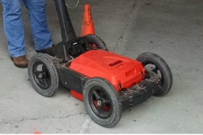
Ground Penetrating Radar (GPR) detects and maps interfaces of contrasting electrical properties, and rebar, conduits, and voids have electrical properties very different from soil and concrete. In general, the method can detect the top and horizontal extent of a void, but GPR data cannot be used to determine the true thickness (depth) of voids. However, relative thickness sometimes can be determined.
Data Acquisition
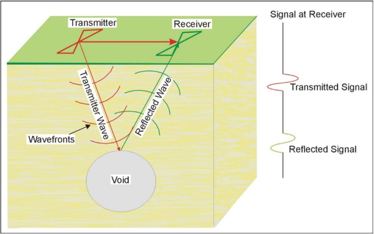
The GPR instrument consists of a recorder and a transmitting and receiving antenna, with different antennae being used to provide different frequencies. The transmitter and receiver antenna and the GPR waves are illustrated in the figure below. An air or water-filled void will almost certainly provide a dielectric contrast with the host rocks.
GPR surveys are conducted by moving the antenna across the ground surface at a normal walking pace. The recorder stores the data as well as presenting a picture of the recorded data on a screen. When conducting GPR surveys, it is usually advisable to have a selection of antennae available and to perform tests to ascertain the most appropriate antenna to use for the survey based on signal penetration and vertical and horizontal resolution. Generally, it is best to acquire data using the highest frequency that provides the required signal penetration. GPR data should be acquired in a grid pattern with the line spacing set to the smallest void of interest for the survey. Acquisition in this manner allows the data to be processed in 2D or 3D formats.
Data Processing
It is possible to process the data, much like the processing done for reflection seismic surveys. Processing might include distance normalization, horizontal scaling (stacking), vertical and horizontal filtering, velocity corrections, and migration. However, depending on the data quality, this may not be necessary since the field records may be all that is needed to observe the cavity. If the dimension of the cavity is of interest, processing is required.
Data Interpretation
The typical GPR signature for an air-filled void is a distinctive high-amplitude GPR reflection. High-amplitude GPR reflections are due to the large contrast in dielectric properties between the slab/pavement/soil and air gaps. Moderate amplitude GPR reflections from the bottom of the slab/pavement are interpreted to be caused by either thin air-filled voids, poor coupling between the slab/pavement and the sub-slab materials, or excessive moisture content in the interphase concrete/soils. Where good contact between the floor slab and sub-slab materials is present, there is typically no strong GPR reflector present. Voids at depth often also exhibit sloped or draped reflectors at the features limit, indicating the downward migration of soil into the feature below.
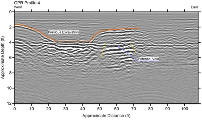
To calculate the depth to the cavity, the speed of the GPR signal in the soil or rock at the site needs to be determined. This can be estimated by using speeds for typical soil/rock types or it can be obtained in the field by conducting a small traverse across a buried feature whose depth is known. A typical GPR record over a void (cavity) is shown in the figure above. The top of the plot represents the current ground surface, the red lines indicate a former ground surface and a filled void, the yellow arrow points to a potential new void forming adjacent to the filled void.
Deliverables
Results of GPR surveys for voids and cavities are typically provided as 2D profiles showing depth corrected sections with interpreted locations of voids, cavities interfaces, objects, and other pertinent features. If the survey has sufficient horizontal coverage, plan views can be generated for to show the spatial distribution of such features.
Advantages
GPR surveys are non-invasive and large amounts of data can be acquired quickly, providing a very high data density at a relatively low cost. GPR data can be recorded quickly, and the data is presented on a screen during the survey allowing its quality to be evaluated and allows for crude in-field interpretation of the data for emergency operations. If the resolution or signal penetration depth is not adequate, then the antenna frequency can be changed rapidly.
Limitations
As described above, The GPR requires a contrast in the electrical properties of the target and the surrounding materials. If the contrast is small, detection is very difficult. Dielectric contrasts will be greater with an air-filled void and least with a void filled with alluvium or water. Penetration of the GPR signal may be severely limited in saturated, electrically conductive ground containing clay. For surveys along roadways, saline conditions resulting from road salt may produce conductive conditions limiting signal penetration. In addition, any metal reinforcement in roadbeds may hinder a survey.
Some low frequency GPR antennae are not shielded, allowing GPR energy to radiate in all directions. Thus, surveys under tree canopies, bridges, or other structures using lower frequency antennae will produce reflections from these overhead features that may interfere with reflections for subsurface features. It may be possible to separate the reflection from the bridge deck or other overhead features from subsurface reflections, providing these two reflection times are significantly different.