Basic Concept
Full Waveform Inversion (FWI) is an advanced seismic imaging and parameter estimation technique that reconstructs high-resolution subsurface models by iteratively minimizing the misfit between observed seismic waveforms and numerically simulated waveforms. Unlike conventional seismic refraction, reflection, or surface wave methods that rely primarily on travel times or dispersion characteristics, FWI utilizes the complete seismic waveform, including amplitude, phase, and frequency content.
FWI can be implemented in either two dimensions (2D) or three dimensions (3D). In a 2D implementation, seismic data are acquired and inverted along one or more vertical profiles to produce high resolution cross-sectional images of the subsurface. In a 3D implementation, dense areal seismic acquisition is performed so that fully 3D subsurface velocity volumes can be reconstructed, allowing complex 3D wave propagation effects to be explicitly accounted for. Both approaches are governed by the same physical principles and inversion framework, with the choice between 2D and 3D determined by project objectives, site complexity, and budget constraints.
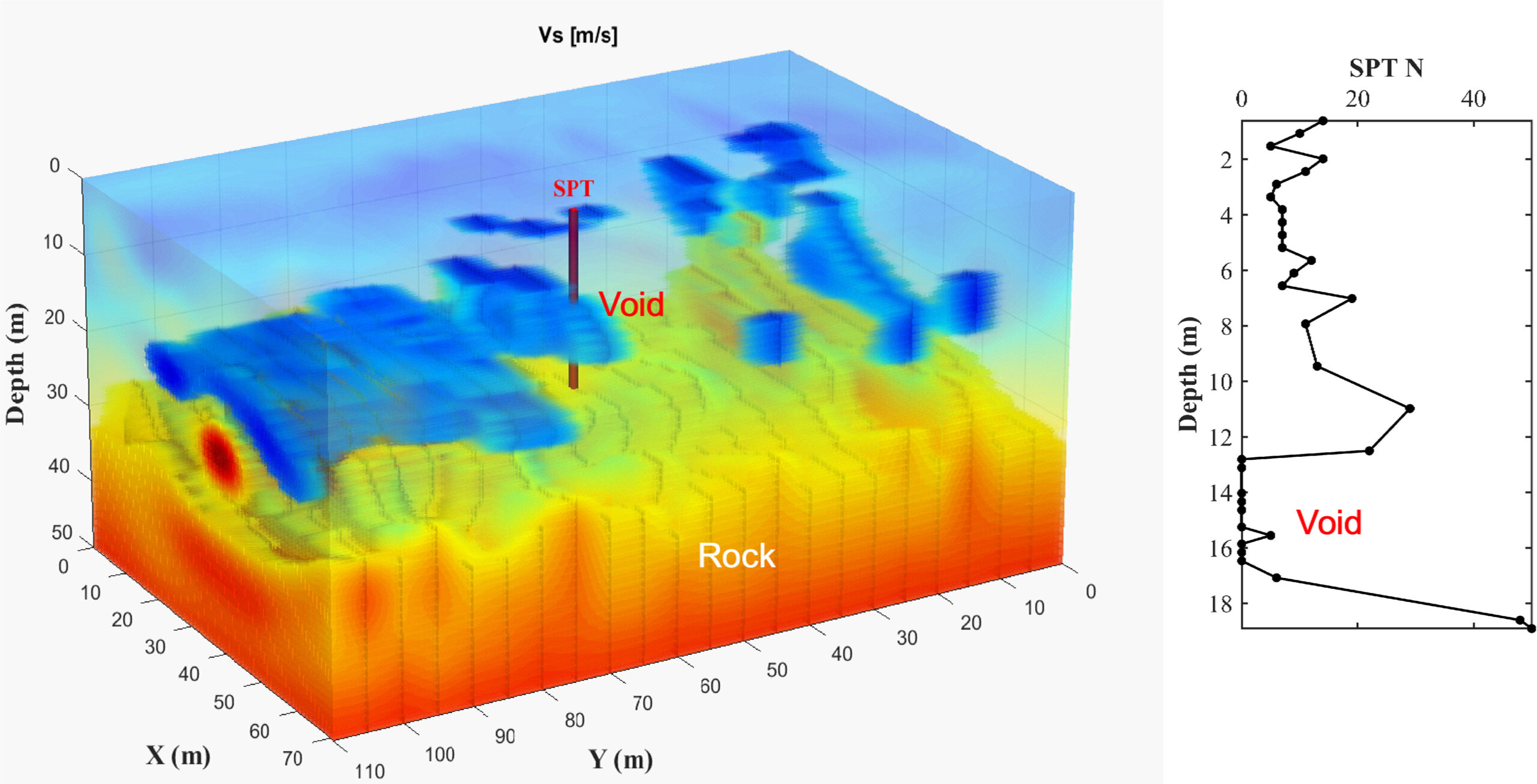
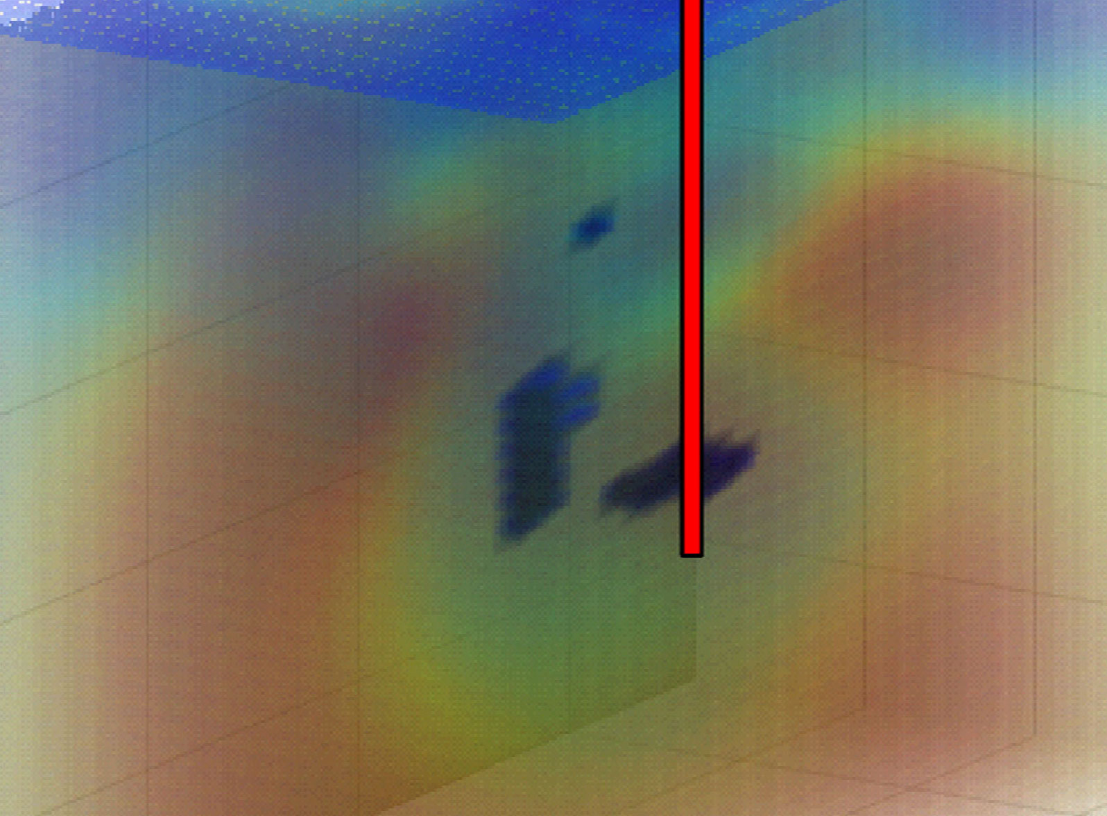
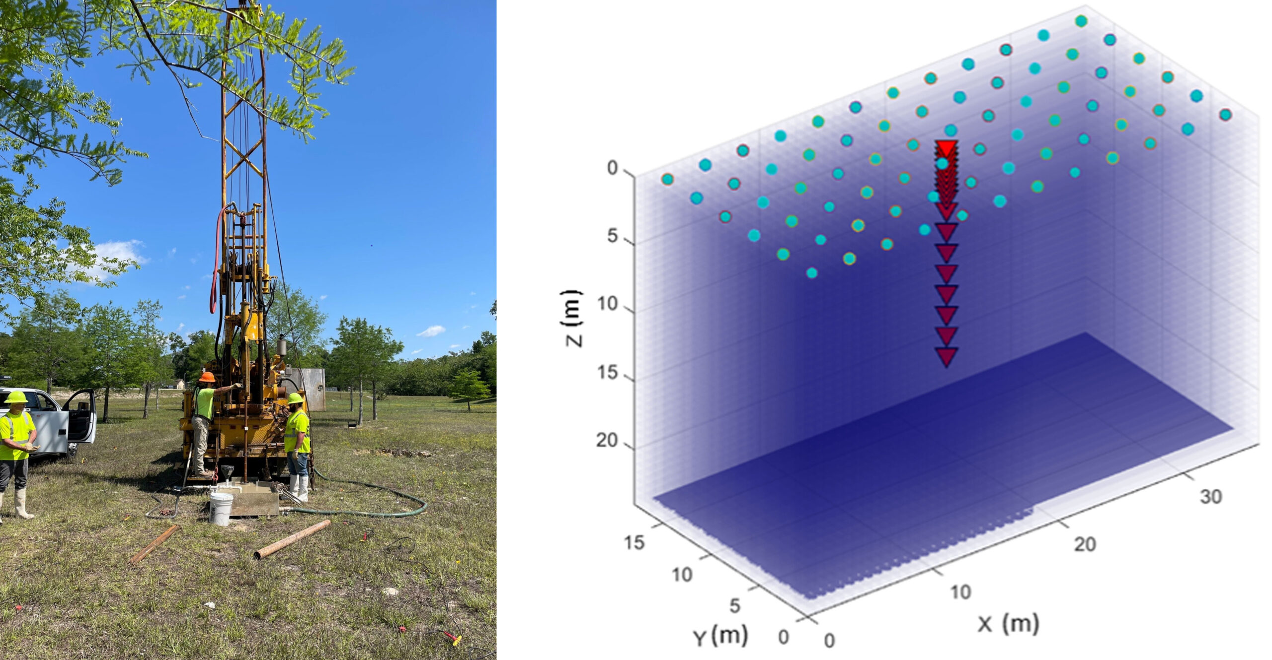
FWI using a borehole source is also called the 3D SPT-seismic method. This approach extends the value of traditional SPT testing, transforming routine SPT operations into a volumetric subsurface imaging tool. By integrating seismic wavefields generated during SPT hammer blows with advanced 3D FWI, this method enables high-resolution imaging of subsurface stratigraphy, stiffness variations, and anomalies surrounding a borehole.
Limitations
FWI requires high quality seismic data with a good signal-to-noise ratio and is more computationally intensive than conventional seismic methods. The results are sensitive to the accuracy of the initial velocity model used to start the inversion. 3D FWI surveys, while offering the highest level of detail, involve greater field effort, higher cost, and increased computational demand compared to 2D surveys.
Measurements and Relevant Physical Properties
FWI estimates fundamental elastic properties of the subsurface, most commonly P-wave velocity (Vp) and S-wave velocity (Vs). In some implementations, attenuation and density may also be estimated. These seismic parameters are directly related to material stiffness, degree of weathering, saturation, and lithology, and they can be correlated with geotechnical indices such as stiffness moduli and penetration resistance.
Data Acquisition
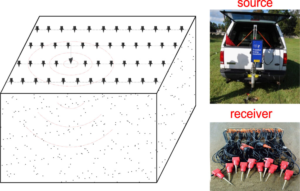
FWI requires dense seismic data acquisition with closely spaced sources and receivers (3-5 m spacing) in order to adequately sample the seismic wavefield. Data are typically collected using controlled seismic sources such as impact hammers, weight drops, propelled energy generators, vibroseis units (surface source), or SPT-rig (borehole/in-depth source), in combination with dense receiver arrays composed of geophones or distributed acoustic sensing (DAS) channels. High spatial sampling and broad frequency content are required to resolve shallow features and laterally variable subsurface conditions.
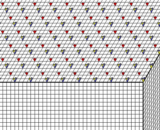
For 2D FWI surveys, seismic sources and receivers are deployed along linear profiles, making this approach well suited for corridor style investigations such as roadways, levees, embankments, and utility alignments. For 3D FWI surveys, sources and receivers are distributed over an area in a grid or pseudo3D configuration, enabling volumetric imaging where subsurface conditions are highly heterogeneous or inherently 3D.
3D SPT-seismic surveys are conducted concurrently with standard SPT drilling operations and do not require additional invasive testing. During SPT advancement, seismic waves generated by each hammer blow on the drill rod are used as subsurface seismic sources. These wavefields are recorded at the ground surface using a dense two-dimensional array of vertical geophones arranged around the borehole location.
Data Processing
Initial data processing typically includes geometry assignment, trace editing, filtering, amplitude normalization, and noise attenuation. Following preprocessing, an initial subsurface velocity model is developed, often using results from refraction tomography or surface wave analysis. Numerical forward modeling of seismic wave propagation is then performed using elastic or acoustic wave equations. The difference between the observed and simulated waveforms is quantified, and the subsurface model is iteratively updated until the difference is minimized.
To ensure stable convergence and reliable results, FWI is commonly performed using a multiscale inversion strategy in which lower frequency data are inverted first, followed by progressively higher frequencies. This approach reduces the risk of cycle skipping and improves the robustness of the final model.
Data Interpretation
The final results of FWI consist of high-resolution seismic velocity models presented as 2D cross sections or 3D volumes. These models are interpreted in terms of stratigraphy, stiffness contrasts, and anomalous zones (voids/problematic soils). Sharp velocity gradients often correspond to soil–rock interfaces, weathering fronts, or void boundaries. Compared with conventional seismic methods, FWI provides superior resolution and improved sensitivity to thin layers and embedded low velocity zones.
For 3D applications, the ability to examine the subsurface using horizontal depth slices and vertical cross sections allows for more reliable interpretation of complex geologic features and increases confidence in engineering decision making.