Subsurface conditions often vary significantly over short distances, particularly in karst terrain, reclaimed land, and heterogeneous soil–rock environments. Full Waveform Inversion (FWI) is a useful way to evaluate variations in subsurface stratigraphy. When used for this application, typically the seismic source is an SPT hammer and the method is referred to as the 3D SPT seismic method.
Data Acquisition
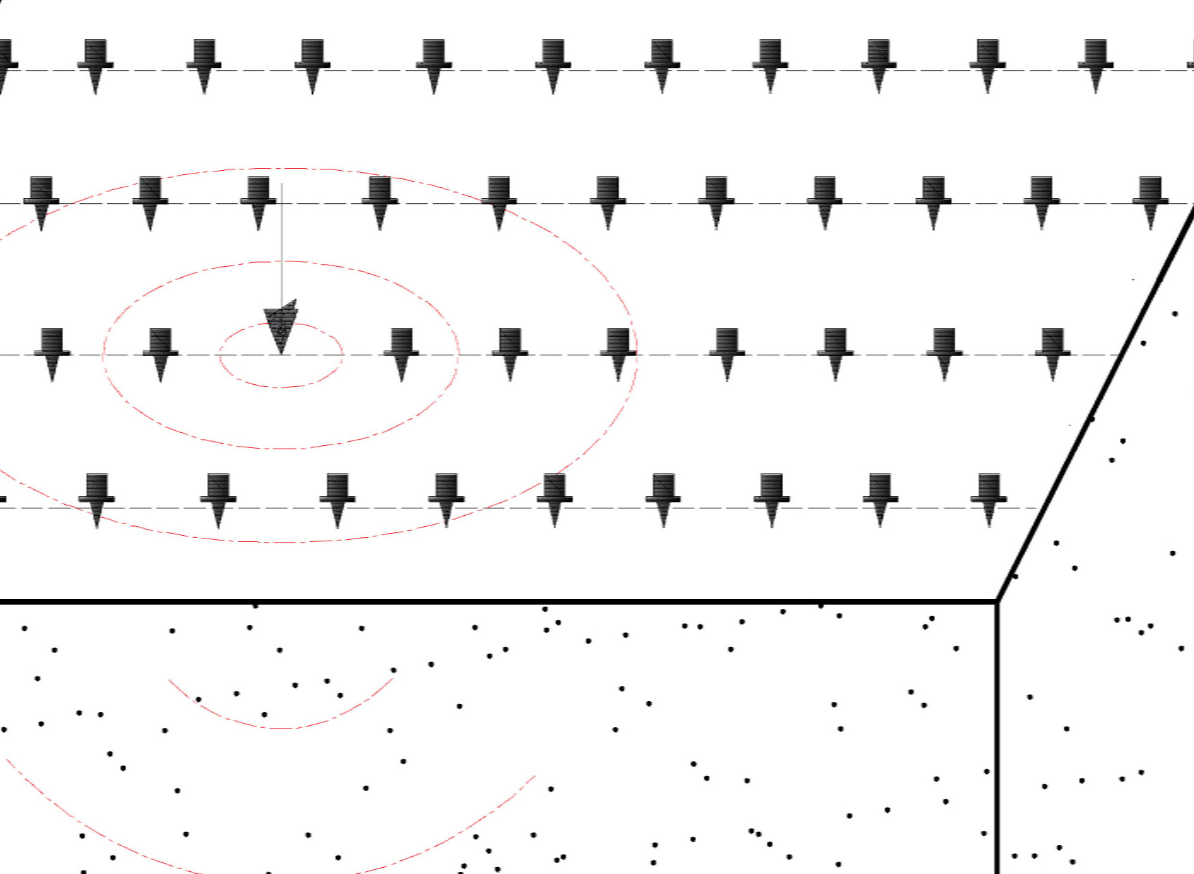
When performing 3D SPT-seismic surveys for mapping stratigraphy, seismic waves generated by each SPT hammer blow on the drill rod are used as subsurface seismic sources. These wavefields are recorded at the ground surface using a dense two-dimensional array of vertical geophones arranged around the borehole location.
The geophone array is deployed in a rectangular or square grid to provide adequate spatial sampling and azimuthal coverage for three-dimensional imaging. Seismic recordings are triggered directly from the SPT hammer with a seismic trigger attached to drill rod. Multiple hammer blows at the same depth are commonly stacked to improve signal-to-noise ratio. Recording time windows are selected based on the expected depth of investigation and anticipated subsurface wave velocities, allowing body waves, reflected energy, and scattered waves to be captured.
Data Processing
Initial processing of SPT-seismic data includes geometry assignment, quality control, filtering, and noise suppression. The processed waveforms are then analyzed using a 3D full waveform inversion framework. An initial subsurface velocity model is constructed, typically assuming a layered soil–rock profile informed by SPT data.
The inversion iteratively updates shear-wave velocity and, where applicable, compressional-wave velocity within a 3D volume surrounding the borehole. A multiscale inversion strategy is employed, beginning with lower frequencies to establish the background velocity structure and progressively incorporating higher frequencies to resolve finer-scale features. This approach improves convergence stability and enhances sensitivity to localized anomalies.
Data Interpretation
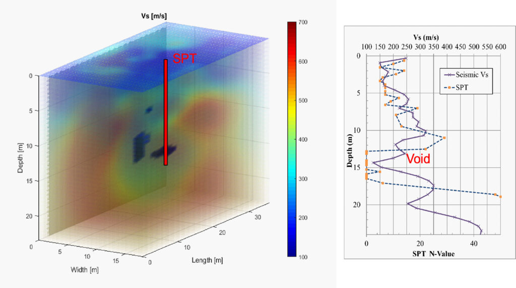
The results of a 3D SPT-seismic survey consist of volumetric velocity models that extend laterally outward from the borehole and vertically to the full depth of SPT penetration. These models are interpreted to identify soil–rock interfaces, variations in material stiffness, and anomalous low-velocity or disrupted zones indicative of voids, weak soils, or weathered rock.
Because the seismic sources originate within the subsurface rather than at the ground surface, the method provides improved resolution at depth compared to surface-based seismic techniques. The three-dimensional nature of the results allows features located away from the borehole to be detected, including anomalies that would not be intersected by drilling alone. Correlation of inverted shear-wave velocity profiles with measured SPT blow counts further enhances interpretation confidence and enables spatial extrapolation of geotechnical parameters.
Deliverables
Deliverables from a 3D SPT-seismic investigation typically include processed seismic datasets, three-dimensional shear-wave velocity volumes, two-dimensional cross sections and horizontal depth slices, and interpreted figures highlighting key subsurface features. A technical memorandum is provided summarizing the survey objectives, acquisition configuration, processing and inversion methodology, interpretation results, and identified limitations. Where applicable, correlations between seismic velocity and SPT N-values are presented to support design applications.
Advantages
The 3D SPT-seismic method significantly enhances the information obtained from conventional SPT testing by providing spatially continuous subsurface imaging around a single borehole. The approach is cost-effective because it leverages seismic energy generated during routine SPT operations without requiring additional drilling or seismic sources. The method offers sub-meter-scale resolution, improved sensitivity to voids and weak zones, and the ability to image subsurface conditions up to tens of meters laterally from the borehole. It is particularly well suited for complex geological environments where subsurface variability cannot be reliably captured by point measurements alone.
Limitations
The quality and resolution of 3D SPT-seismic results depend on data quality, array geometry, and subsurface conditions. Highly attenuative soils, strong cultural noise, or limited site access may reduce data quality. The method requires sufficient hammer energy transfer to generate usable seismic signals, which may be reduced in very loose or voided intervals. As with all geophysical methods, interpretation is non-unique and is most reliable when integrated with borehole logs, laboratory testing, and site-specific geological information.