Cross-Borehole Seismic Tomography is used for high resolution seismic velocity and/or attenuation imaging of the subsurface between boreholes.
Data Acquisition
Typical field operation consists of placing a string of receivers (geophones or hydrophones) in one borehole and moving a source systematically in the opposite borehole from bottom to top. The receiver string is then shifted to the next depth location and the test procedure is repeated until all data for all possible source-receiver combinations are acquired. Cross-borehole seismic tomography is a useful tool to gather data on existing foundations or other structures located between the borings. When conducting these surveys, boreholes need to be installed on each side of the foundation or structure to be tested. As a good rule of thumb, the hole separation should not be more than 50% of the borehole depth and significantly closer if the foundation and structures are small.
Data Interpretation
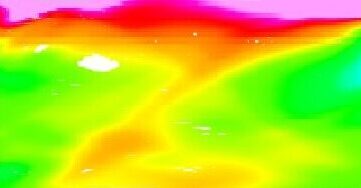
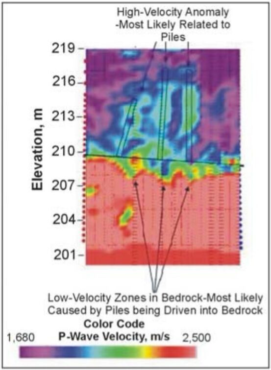
The left panel of the figure below is a tomographic survey designed to investigate the foundation of an existing bridge. In this example, cross-borehole seismic tomography surveys were conducted by pairing a seismic source in one borehole and a string of receivers in an adjacent borehole. Steel or concrete piles that existed within the surveyed area were indicated in the tomograms. The pile group, as depicted in the left panel, appeared as relatively higher seismic velocity anomalies within the fill and soil material above the bedrock. There was also a clear indication of low-velocity anomaly pockets in the top of the bedrock where the piles were driven into the bedrock, due to disturbance of the rock as a result of driving. The seismic tomography survey confirmed that the piles were bearing on rock, and, in fact, indicated that they were embedded several feet into the bedrock.
The example shown on the right panel on the figure shows the results of a tomographic survey designed to investigate the depth of four drilled shafts supported by a pile cap under a bridge column. The shafts were originally thought to be socketed 2m into the bedrock. The tomogram shows that the shafts are set into rock as evidenced by the low velocity pockets within the higher velocity bedrock zone.
Deliverables
A cross-borehole seismic tomography report shouldl primarily focus on discussing the findings on the survey, and interpretation of the various tomographic panels. Descriptions of equipment and software used, test setup, procedures, data acquisition details, and data processing schemes should also be discussed.
Advantages
Tomography provides high-resolution two-dimensional area or three-dimensional volumetric imaging of target zones for foundation assessment. Tomography can be used even if direct access to the foundation is not possible.
Limitations
Tomography is data-intensive and specialized 3-D analysis software is required for true three-dimensional imaging. Artifacts can be present due to limited ray coverage, near the image boundaries.