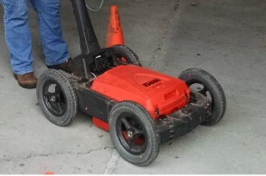
GPR uses electromagnetic waves to assess the integrity and thickness of concrete, masonry, and timber structures. For concrete structures, GPR can be used to map the locations and depths of rebar and tendons, map the reflectivity of the rebar and tendons, and to locate voids within and underneath slabs.
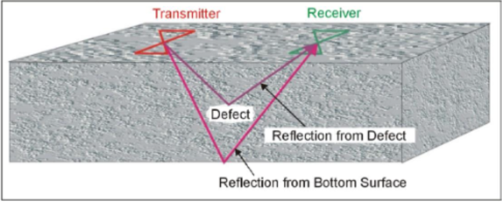
Data Acquisition
GPR surveys are conducted by moving the antenna over the surface of the object to be surveyed. For concrete surveys, high frequency systems (1 GHz to 3 GHz) are typically used. Where thicker concrete slabs are present, lower frequency systems can be used. The system records the data and displays the data on the screen. The GPR systems use either a survey wheel or an optical encoder for positioning. Recoding time windows should be set according to the depth of interest and the expected velocity of the material.
Data Processing
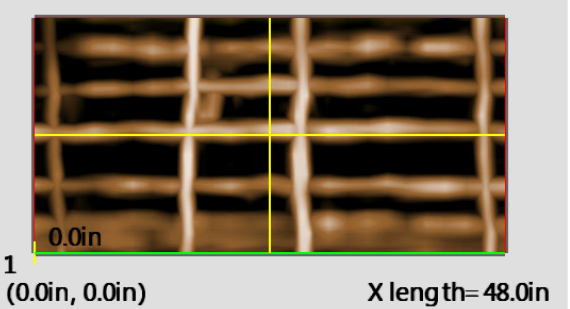
Processing GPR records for the purpose of locating reinforcement within concrete is typically not required. Some current GPR systems can process and present 3D results in terms of rebar location and depth in real-time as shown in the figure above. Processing may be required where the objective of the surveys is to detect delamination within concrete, or to map areas of degraded concrete or rebar.
Data Interpretation
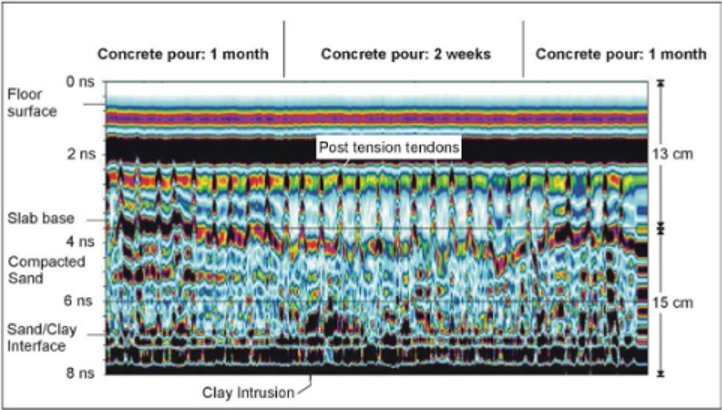
GPR data is usually interpreted by visually inspecting the records and recognizing reflections typical of features such as reinforcement, structural elements such as grade beams or post tension cables, and from the base of the concrete slab. The figure below shows GPR data from a post-tension tendon survey at two different times after the concrete pour showing how the GPR signal changes as the water content of the concrete changes. In this case, the penetration of the GPR signal was to a depth of about 20 cm.
Deliverables
Results of GPR surveys are typically provided as 2D or 3D plots of the locations of the detected features. For NDT applications, such features include the thickness of the concrete slab, the vertical and horizontal position of rebar and post tension cables withing the concrete, and the vertical and horizontal positions of zones of delamination in the concrete, and voids below the concrete. In some cases, real-time interpretation is completed in the field and the locations of the above features are marked on the slab at the time of the survey.
Advantages
GPR is a quick and economical test method used for condition evaluation and high-resolution imaging in or below structures. A large volume of data can be acquired in a short time frame providing high spatial resolution for relatively low cost. The method can be used to rapidly map the locations of rebar and tendons in the field. Only one-sided access is required for this method, and it can be conducted on floors, walls, or ceilings.
Limitations
The depth of penetration depends on the frequency of the GPR signal used and the resistivity (or its inverse, conductivity) of the material being investigated. Since the higher frequencies provide better resolution, the objective is to use a frequency as high as possible, consistent with the required depth of investigation.
Concrete may have resistivities that vary substantially depending on the moisture and salt content. Wet concrete may contain significant amounts of saline water that will have much less penetration than dry concrete. Some floor coverings can also severely limit GPR signal penetration.