
Basic Concept
Seismic reflection methods are active-source geophysical methods that employ an above-ground source and receiver array to transmit seismic energy into the Earth and record the response. A seismic reflection occurs when the combination of the density and velocity of subsurface geologic material (impedance) is sufficiently different from one geologic layer to the next. Seismic reflection methods were developed for oil and gas exploration applications. More recently, these methods have seen greater use as near-surface investigatory tools due to technological advances that increase their ability to produce high-resolution images of the subsurface.
Two main types of seismic waves are commonly used: compressional waves (P-waves) and shear waves (S-waves). The choice between P-waves and S-waves depends on the engineering application and the specific subsurface conditions. P-waves typically have higher velocities and are more commonly used, while S-waves provide higher resolution of shallow subsurface features and are less affected by pore fluids.
Seismic Reflection allows for the identification of bedding planes, faults, voids, and other geological discontinuities that are critical for site selection, hazard assessment, and design. In heterogeneous or structurally complex areas, reflection data can reveal features like fractured zones, dipping beds, and buried channels that may not be easily detected with sparse borehole sampling or other lower resolution geophysical methods. The method is capable of imaging multiple subsurface layers with good vertical and horizontal resolution. Depending on the type of source, seismic reflection may be used to effectively image deep subsurface structures well beyond the range of other less sensitive near surface engineering geophysical methods.
Recent advances in nodal recording and lightweight source technologies have made it possible to consider 3D surveys for high resolution near surface applications.
Limitations
Historically, the seismic reflection method has been more expensive (in terms of resource allocation and time) compared to other geophysical methods. A 2D deployment is often employed to generate 2D subsurface cross sections.
Understanding the operational limitations is essential for establishing realistic expectations and proper planning in engineering projects. Data quality may be limited at sites with ambient coherent noise such as traffic or machinery. Also, in extremely shallow investigations (e.g., <2–5 m depth), seismic reflection may be less effective than refraction or surface wave methods. Seismic reflection surveys are typically more costly on a linear footage basis than other engineering geophysics methods, and processing of seismic data demands experienced geophysicists with specialized software that may be too time consuming for project constraints.
Measurements and Relevant Physical Properties
The physical process of a reflection is illustrated below, where raypaths (representative of the incident energy) passing through successive layers are shown. Seismic reflections are caused by variations in impedance between different geological layers. The impedance is calculated as the product of the medium’s density and the velocity of the energy that passes through that medium. When seismic waves encounter a boundary where an impedance change exists, some of the wave energy is reflected back towards the surface and is recorded by receivers.
The effectiveness of source penetration is inversely proportional to the radius of the propagating wavefront as it enters the Earth and is scattered back to the recording array. Consequently, attenuation acts to weaken the reflection response from deeper structures. Reflections recorded at later times from deeper events typically are weaker and have a lower signal-to-noise ratio. Seismic processing and imaging methods help to overcome these limitations.

Data Acquisition
For P-wave surveys, seismic energy is generated using a source such as a hammer blow, weight drop, or controlled explosion. For generating S-waves, specialized sources are required because S-waves involve horizontal particle motion, unlike compressional waves (P-waves), which propagate vertically. The most common seismic sources for S-wave generation include horizontal hammer, weight drop with horizontal coupling, and shear-wave mode Vibroseis, a vibrating seismic wave generator.
The figure below shows a picture of a nitrogen assisted weight drop seismic source for P-wave generation.
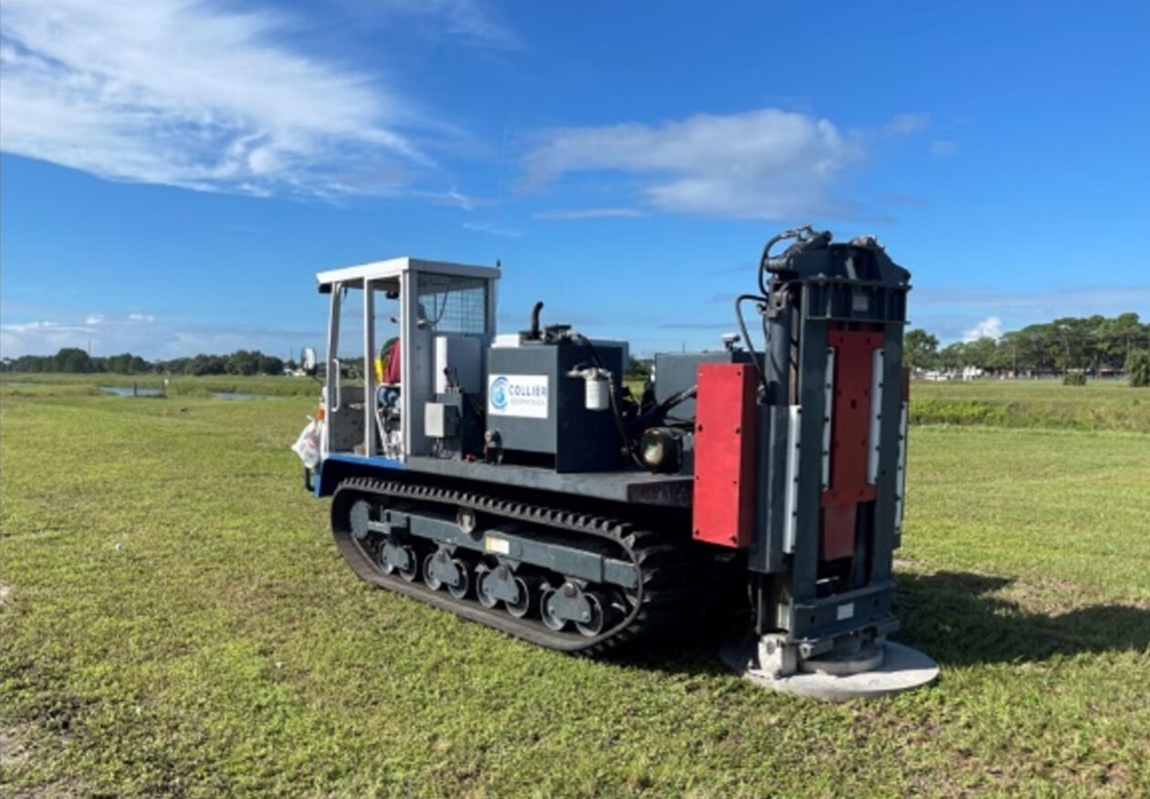
Field data acquisition approach and setup for seismic reflection surveys are highly site specific. Up to a full day of testing with a knowledgeable consultant experienced in shallow seismic work may be required. The objective of these tests is identifiable, demonstrable reflections on the raw records.
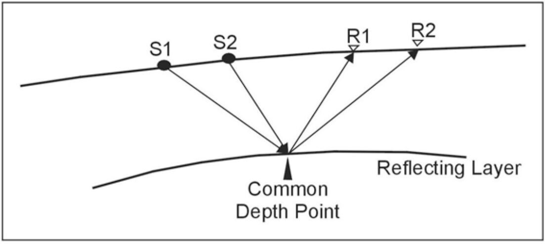
Seismic reflection data is often acquired using the common reflection point, common midpoint (CMP), or common depth point (CDP) method. All terms refer to the same method. This setup is illustrated in the figure below. If multiple source points, S1 and S2, are recorded by multiple receivers, R1 and R2, and the geometry is as shown in the figure, the common reflection point for both raypaths is the same. When processing CMP reflection data, the data is corrected for source-receiver offset, and grouped based on the common subsurface reflection (CMP gather). The result are then summed or stacked to improve the signal to noise ratio.
If all receiver locations are also used as shot points, the multiplicity of data on one subsurface point (called CMP fold) is equal to one-half of the number of recording channels. Thus, a 24-channel seismograph will record 12-fold data if a shot corresponding to every receiver position is shot into a full spread. Thus, for 12-fold data, every subsurface point will have 12 separate traces (seismic record from a single geophone) added, after appropriate time shifting, to represent that point.
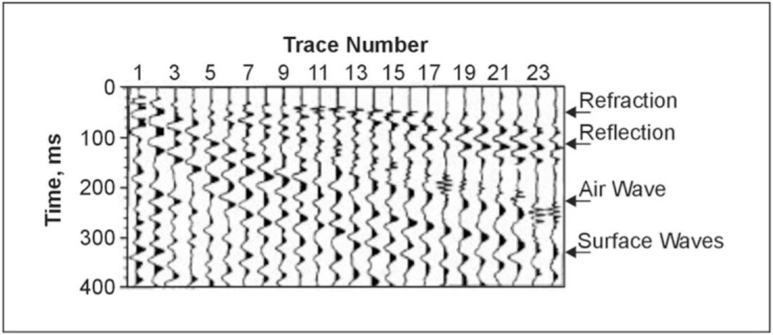
Arrivals on a seismic reflection record can be seen in the figure below. The receivers are arranged to one side of a shot, which is 15 m from the first geophone. Various arrivals are identified on the figure. Note that the gain (amplitude amplification) is increased down the trace to maintain the signals at about the same size by a process known as automatic gain control (AGC). One side of the traces is shaded to enhance the continuity between traces.
Data Processing
The ultimate product of a seismic reflection survey is a corrected cross section of the subsurface with reflection events in their true positions. Processing is typically performed by professionals using special purpose computers and software. A close association of the geophysicist, the processor and the consumer is essential if the results are to be useful. Any boring logs or CPT traces, known depths, results from ancillary geophysical methods, and the expected results should be furnished to the processor and are often very helpful in building an initial estimate of the subsurface velocity field. Multiple iterations of the different processing and imaging steps are expected and necessary to ensure that the final outcome is successful. Processing schemes may vary based on type of survey, objectives, data quality, and geological settings.
One important deliverable for seismic reflection surveys is a true depth section. Seismic reflection data is initially recorded in two-way travel time, i.e. the time it takes for a wave to travel to a reflector (a subsurface layer that it reflects off) and return. To be useful for engineering, these times must be converted to actual depths using velocity models derived from velocity analysis or calibration with boreholes.
In the event digital geophysical borehole log control in the form of sonic and density logs are available, a synthetic seismograph may be generated to compare with and significantly improve the depth calibration of the imaged seismic data.
Data Interpretation
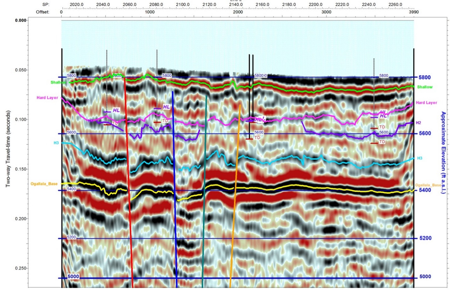
Seismic reflection data interpretation is the process of converting processed seismic records into meaningful geological and geotechnical information. Interpreters identify seismic boundaries and trace them across profiles to build a picture of the stratigraphy and structure. The boundaries are then preferably correlated with borehole information.
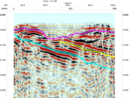
Layer continuity, thickness, and geometry are interpreted to understand sediment deposition and layering. Changes in amplitude or continuity are analyzed since they may indicate differences in lithology, moisture content, or compaction—factors critical in foundation and slope design. Structural features such as faults, folds, fractures, voids, and buried channels can be identified from offsets or terminations in reflection patterns. The figures below show seismic reflection data and interpretations.
Applications

Mapping Voids, Sinkholes, Abandoned Mines and Other Cavities
