
Basic Concept
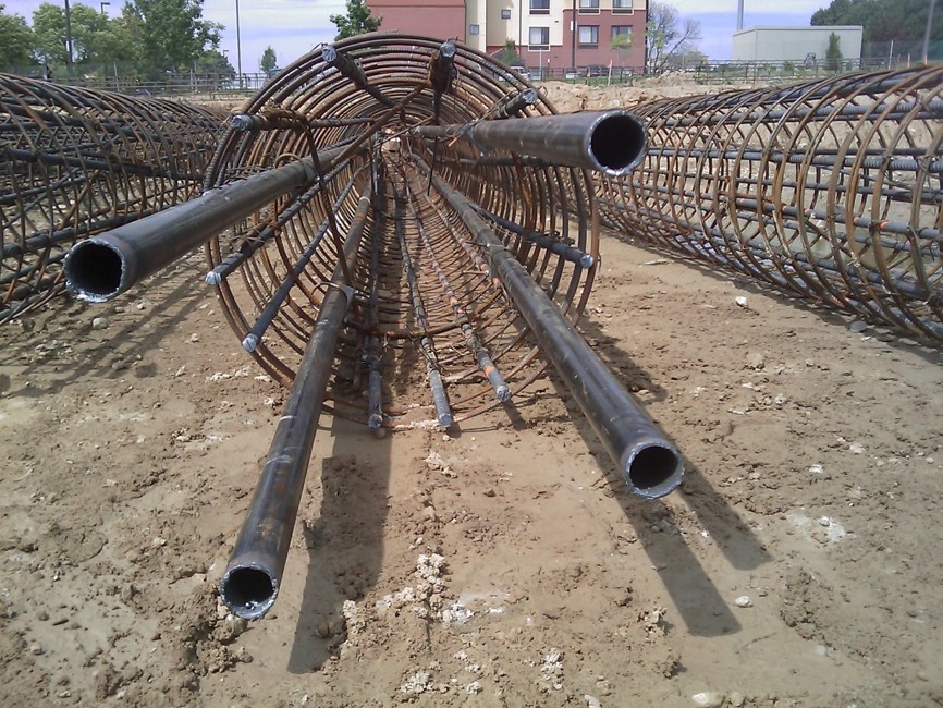
Crosshole Sonic Logging (CSL) is used to assess the integrity of cast-in-place foundations such as drilled shafts, augered cast-in-place piles, and other drilled foundations. Ultrasonic transducers consisting of a transmitter and receiver are lowered down pre-installed access tubes tied to the reinforcing cage and raised at a constant speed to collect wave speed data. CSL can detect voids, weak or adulterated concrete, and other material inclusions.
Limitations
The accuracy of CSL testing is dependent on the success of installing the access tubes and interpretation of the data. Verticality of the access tubes is important for wave speed correlation and anomaly detection. Due to the method of data collection, data is only collected between each tube pair and data outside of the reinforcing cage is unknown. Access tube debonding can cause false positive anomalies, which would lead to unnecessary remediation of the drilled shafts. Additionally, CSL assumes a direct and unobstructed path from the transmitter to the receiver(s) and thus cross bracing or other structural elements can occasionally cause interference or false positives in the data.
Data Acquisition
CSL access tubes (steel or PVC) are cast in the concrete or grout and filled with water after placement. Data is then collected after adequate curing time (typically 3 to 7 days but often as late as 14 days).
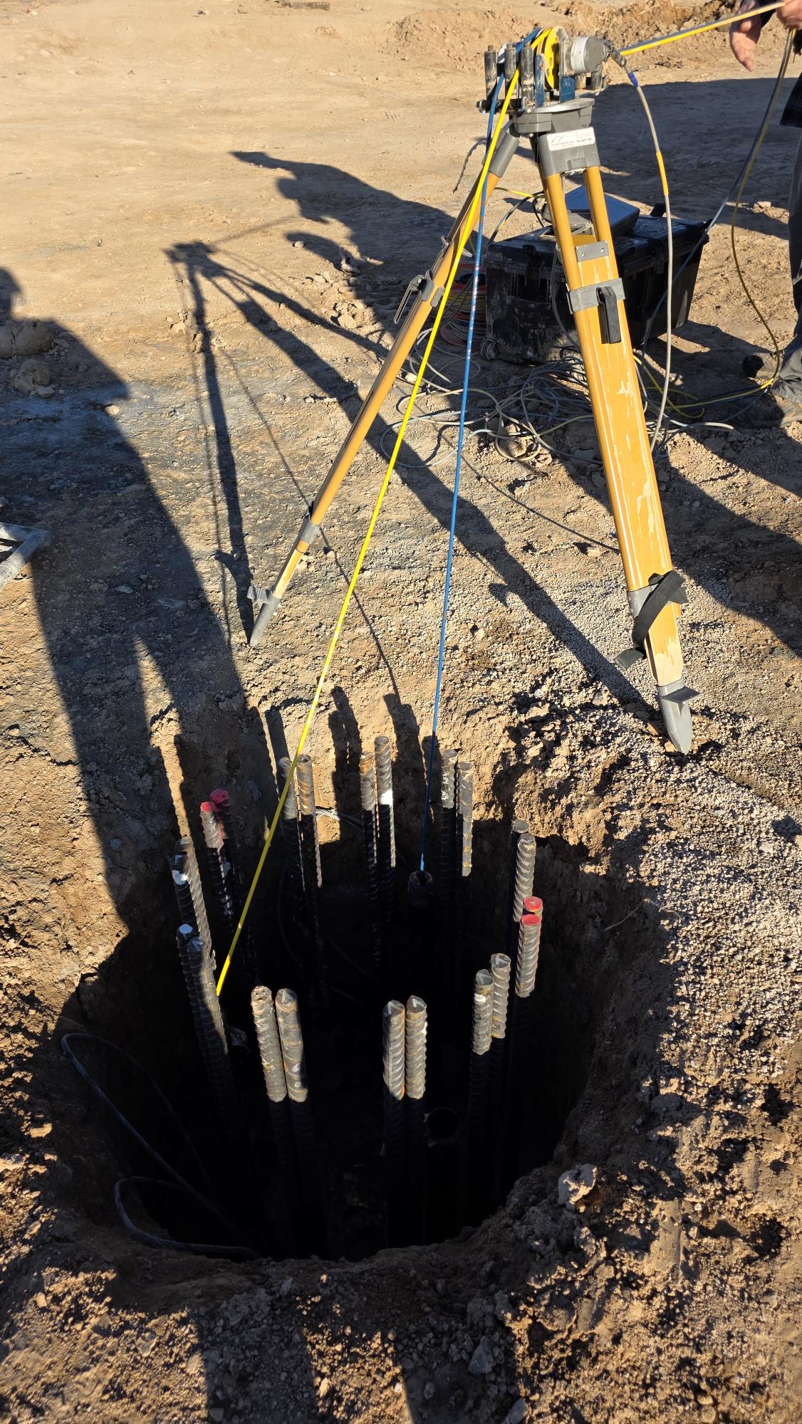
Access tubes are labeled with a corresponding number, with Tube 1 typically oriented to the north and other tubes consecutively numbered clockwise. The tube lengths are measured with a weighted tape, and a standard tape is used to measure the distance between the access tubes. This data is then entered into a data acquisition device. During testing, a transmitter emits high-frequency acoustic pulses that travel through the concrete and are received by a receiver(s) in an adjacent tube(s). The CSL system records signal arrival time, amplitude, and waveform characteristics, which are then processed to generate velocity profiles.
Data Processing
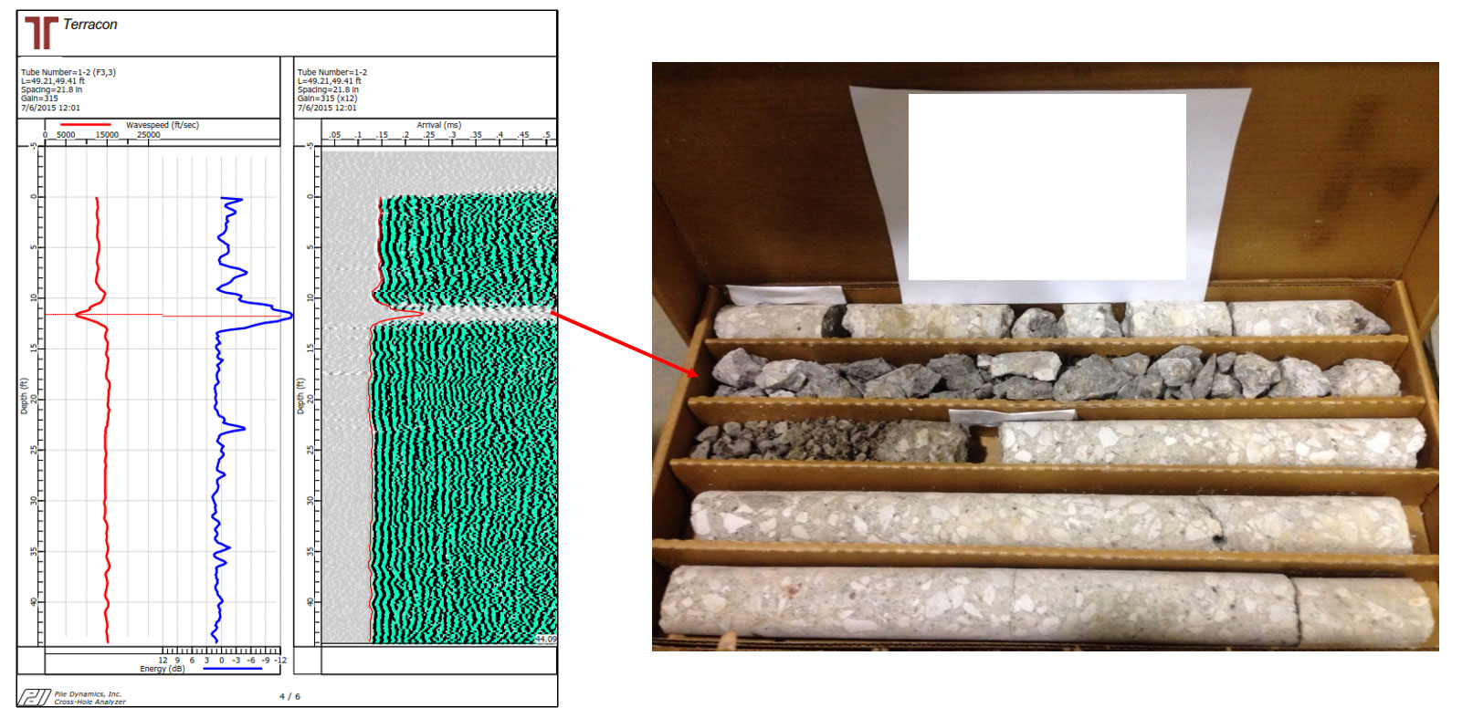
The collected data is processed in specialized software on the computer. The top of the pile is “trimmed,” which means removing noisy data from the access tubes above the top of the pile. The first arrival time (FAT) is then chosen for the wave data taken throughout the drilled element. The data is presented in a “waterfall diagram” where the 1D first time arrival data is depicted in a 2D format for the length of the structure. After the first arrival times are chosen, filtering and defect analysis is also performed.
Data Interpretation
Interpretation of CSL data is typically based on the FAT over the length of the drilled element. Signal strength can also be assessed by looking at the signal amplitude. When signal loss occurs, it indicates an energy and/or velocity reduction which often corresponds to an anomaly in the pile. Engineering judgement is required to evaluate anomalies or reductions in FAT or energy that are observed in the data.
Applications

Integrity Testing of New Foundations