Basic Concept
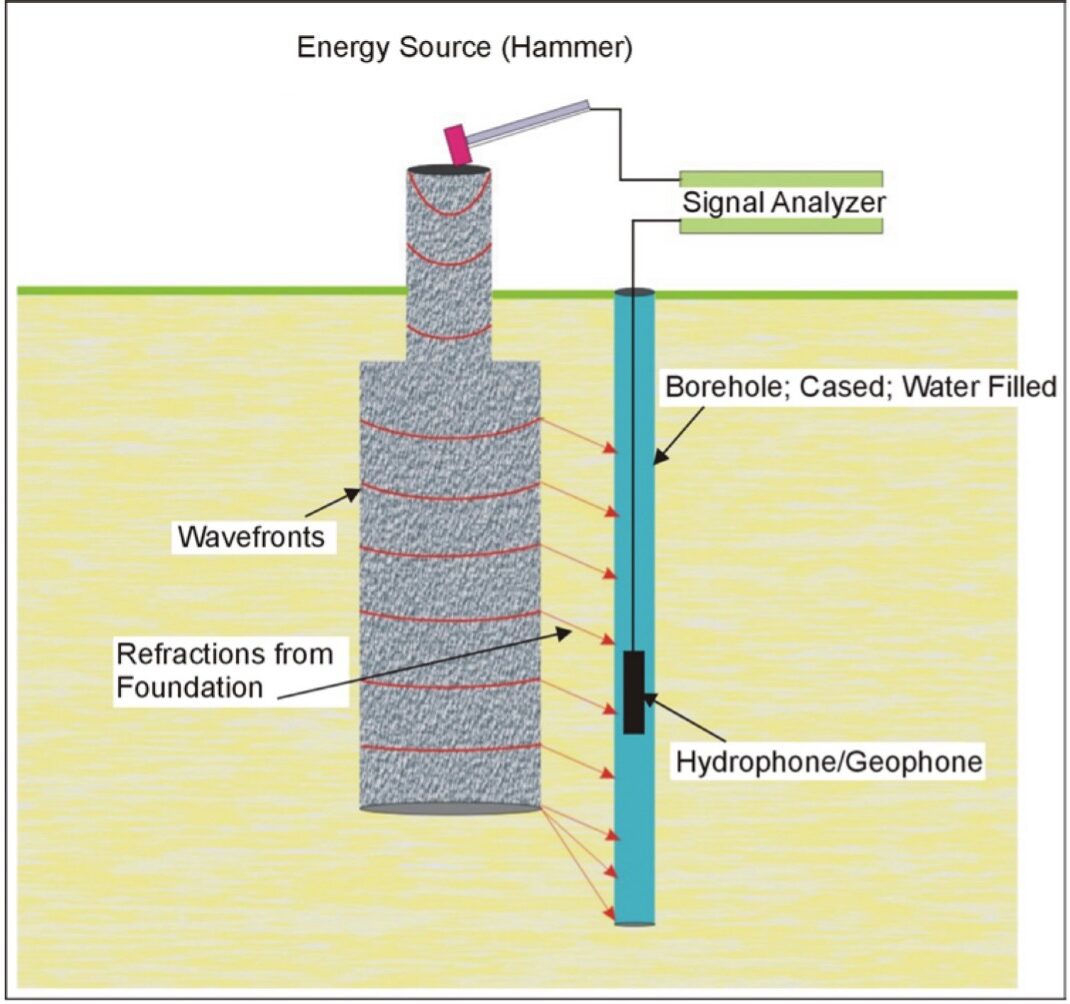
The Parallel Seismic (PS) method is a borehole test method for determining depths of foundations or piles, and to detect major anomalies within a foundation. To employ the PS method, a hammer impact is applied at any part of the exposed structure that is connected to the foundation (or applied to the foundation itself, if accessible). A hydrophone or a three-component geophone located in a nearby borehole records the compressional and/or shear waves traveling down the foundation. Therefore, the PS test requires drilling a 2-4-inch diameter hole as close as possible to the foundation being tested (preferably within 5 feet).
PS tests can be performed on concrete, wood, masonry, and steel foundations. Some portion of the structure that is connected to the foundation must be exposed for the hammer impacts. The method can be used even if the foundation tops are not accessible or when the piles are too long and slender (such as H piles or driven piles) to be testable by sonic echo technique.
PS method depends on the variability of the velocity of the surrounding soil and the spacing between the borehole and the foundation element. Depths are normally determined with 95% accuracy or better.
Limitations
A borehole is needed for PS tests, which adds to the cost of the investigation (unless borings are also required for other geotechnical purposes). The borehole should be within 5 feet of the foundation, which sometimes cannot be achieved. Note that for very uniform soils (such as saturated sands), a successful test can be performed with up to 15 to 20 feet spacing between the source and the borehole. As the borehole moves away from the foundation, interpretation of the PS data becomes more difficult, and the uncertainty in the tip depth determination becomes greater.
Measurements and Relevant Physical Properties
The PS method measures P- or S-wave velocities for the foundation and soil below the foundation. Combining these velocity measurements and unit weight for the foundation materials, low-strain elastic moduli can be calculated such as Bulk and Shear Modulus, Poisson’s Ratio, and Youngs Modulus. The data can be used to determine foundation depth, and to detect major anomalies within a foundation.
Data Acquisition
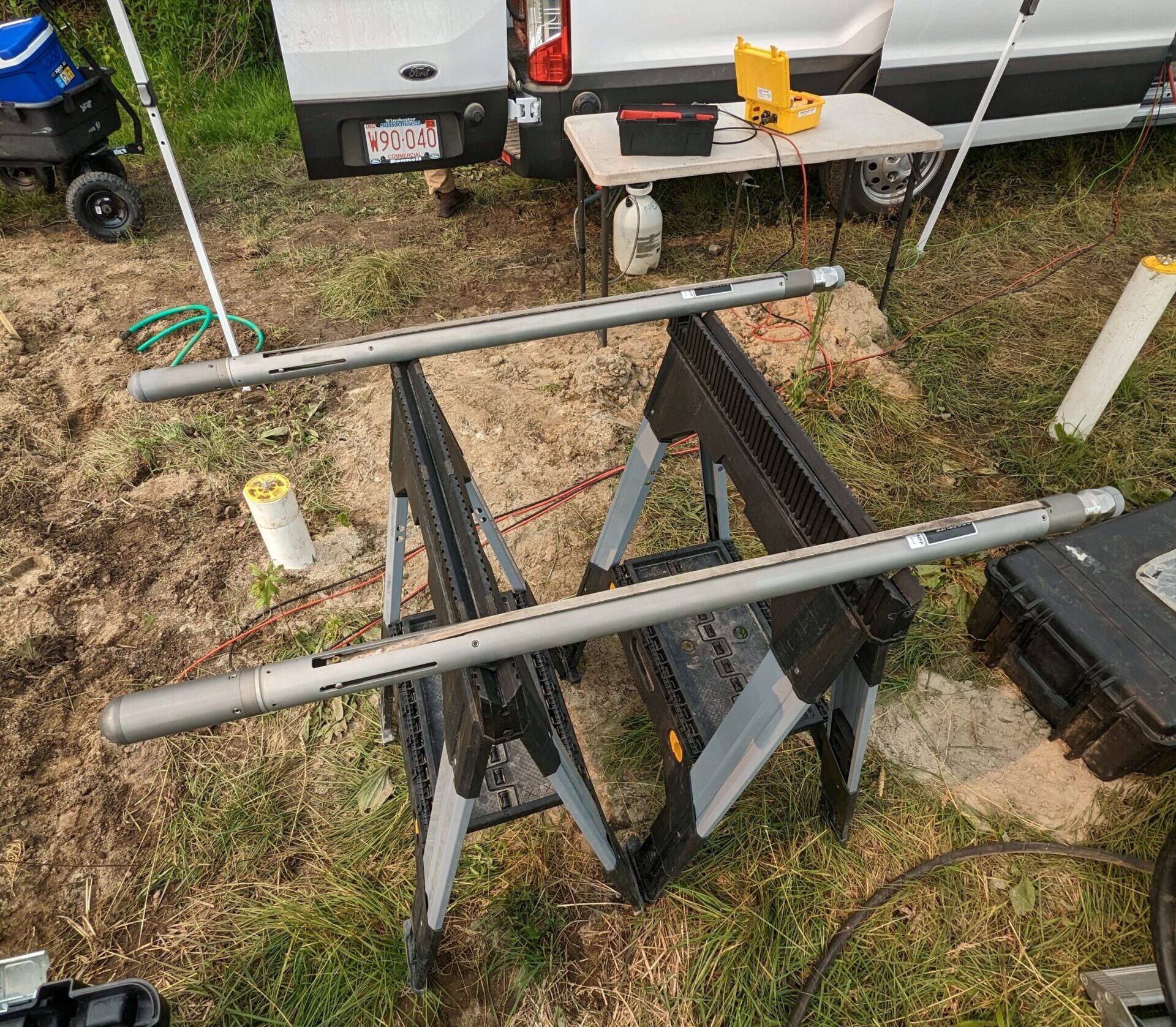
The field setup for PS tests is shown below. In a PS test, a hammer strikes the structure, and the response of the foundation is monitored by a hydrophone or a geophone receiver placed in the borehole. The borehole should be within 5 feet of the foundation and extend at least 10 to 15 feet below the expected bottom of the foundation. If hydrophones are used, the hole must be cased, capped at the bottom, and the casing and hole filled with water. For geophone use, the hole must usually be cased and grouted to prevent the soil from caving in during testing.
A signal analyzer records the hammer input and the receiver output. The receiver is first lowered to the bottom of the hole, and a measurement is taken. Then, the receiver is moved up 1-2 feet, and the second measurement is made. This process continues until the receiver has reached the top of the boring. If needed, the hammer strikes can be repeated multiple times at each location to stack the records and thereby improve the signal-to-noise ratio.
Data Processing
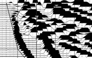
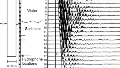
Analysis of the PS data is performed in the time domain. In PS tests, one relies on identifying direct arrival times of compressional and shear waves at the receiver locations, as well as the wave amplitudes. The PS tests are performed at 1-2 feet vertical receiver intervals in the borehole. The first arrival times are plotted as a function of depth. Geophysical processing techniques can be used to help optimize the data. These techniques include Automatic Gain Control (AGC) and frequency filtering to enhance weak events.
Data Interpretation
Data interpretation for parallel seismic testing typically requires evaluating the time-arrival-versus-depth plot to determine changes in slope, which may indicate foundation depth and/or anomalies. More details on interpretation for specific applications can be found in the application pages linked on the right.