
Basic Concept
Crosshole seismic testing is a method used to assess properties of a material by measuring the travel time of seismic waves between boreholes. It allows for development of detailed in situ seismic wave velocity profiles for site-specific investigations and material characterization of man-made materials, soil deposits, or rock formations, and for evaluation of near-surface bulk compressibility and shear strength of soils and rock. It is commonly used to define in-situ shear wave velocity profiles for engineering investigations associated with earthquake engineering. Crosshole seismic testing is standardized in ASTM D4428.
Crosshole seismic testing requires, at a minimum, a pair of boreholes that are instrumented with a seismic source in one boring, and seismic receivers in the other(s). The typical approach is to measure the first break / first arrival of seismic energy traveling from the source to the receiver borehole. In this manner, seismic velocities are simply a measure of the distance between boreholes and time traveled by the respective wave type, to produce a one-dimensional (1D) velocity graph versus depth. Note that the ASTM standard requires three boreholes to allow for optimal data collection.
Crosshole seismic testing has the unique advantage of sampling a limited volume of material at each test depth. Thus, the final result is a significantly more detailed and accurate in-situ seismic (P- and/or S-wave) velocity profile than can be obtained from other seismic methods.
Limitations
The primary challenges encountered during crosshole testing are typically related to the placement and completion of multiple drill holes. Crosshole seismic tests are not applicable at sites where noninvasive techniques are required due to hazardous subsurface conditions.
Seismic data for crosshole testing requires considerably more waveform interpretation than other seismic methods because refraction events from high-velocity layers either above or below a low-velocity layer must be identified and the first-arrival velocity corrected. Direct-wave arrivals are easily recognized (even with low-amplitude refracted arrivals) as long as the appropriate field equipment is utilized for preferential generation of P-waves or polarized SV or SH-waves. The ASTM standard of three minimum boreholes and specified spacing allows for optimal correction and evaluation of in situ P- and S-wave velocities for each material layer at depth.
Measurements and Relevant Physical Properties
Crosshole seismic testing determines the compressional (P-) and/or shear (S-) wave velocity of materials. It is generally conducted in the near surface (upper hundred meters) for site-specific engineering applications. All of the dynamic elastic moduli of a material (i.e. bulk and shear modulus, poisson’s ratio, and young’s modulus) can be determined from knowledge of the in-situ density, P-, and S-wave velocity. Therefore, since procedures to determine material densities are standardized, acquiring detailed seismic data yields the required information to analytically assess a site. Low-strain material damping and inelastic attenuation values can also be obtained from cross-hole surveys.
Crosshole seismic testing is used to develop P- or S-wave velocity profiles. Combining these velocity measurements and unit weight for the inter-borehole materials, low-strain elastic moduli can be calculated such as Bulk and Shear Modulus, Poisson’s Ratio, and Youngs Modulus.
Data Acquisition
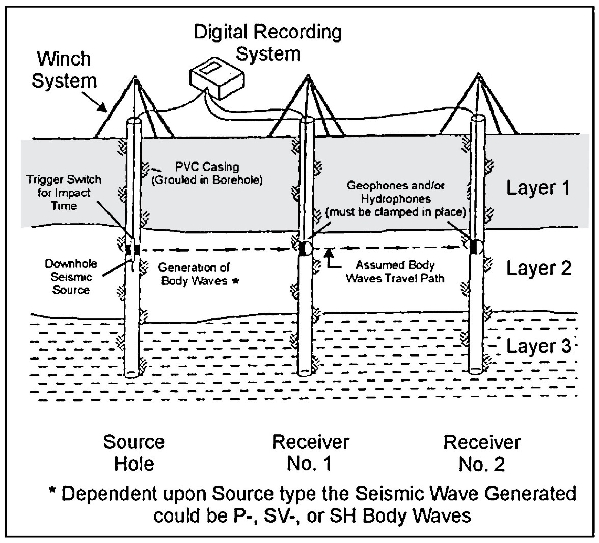
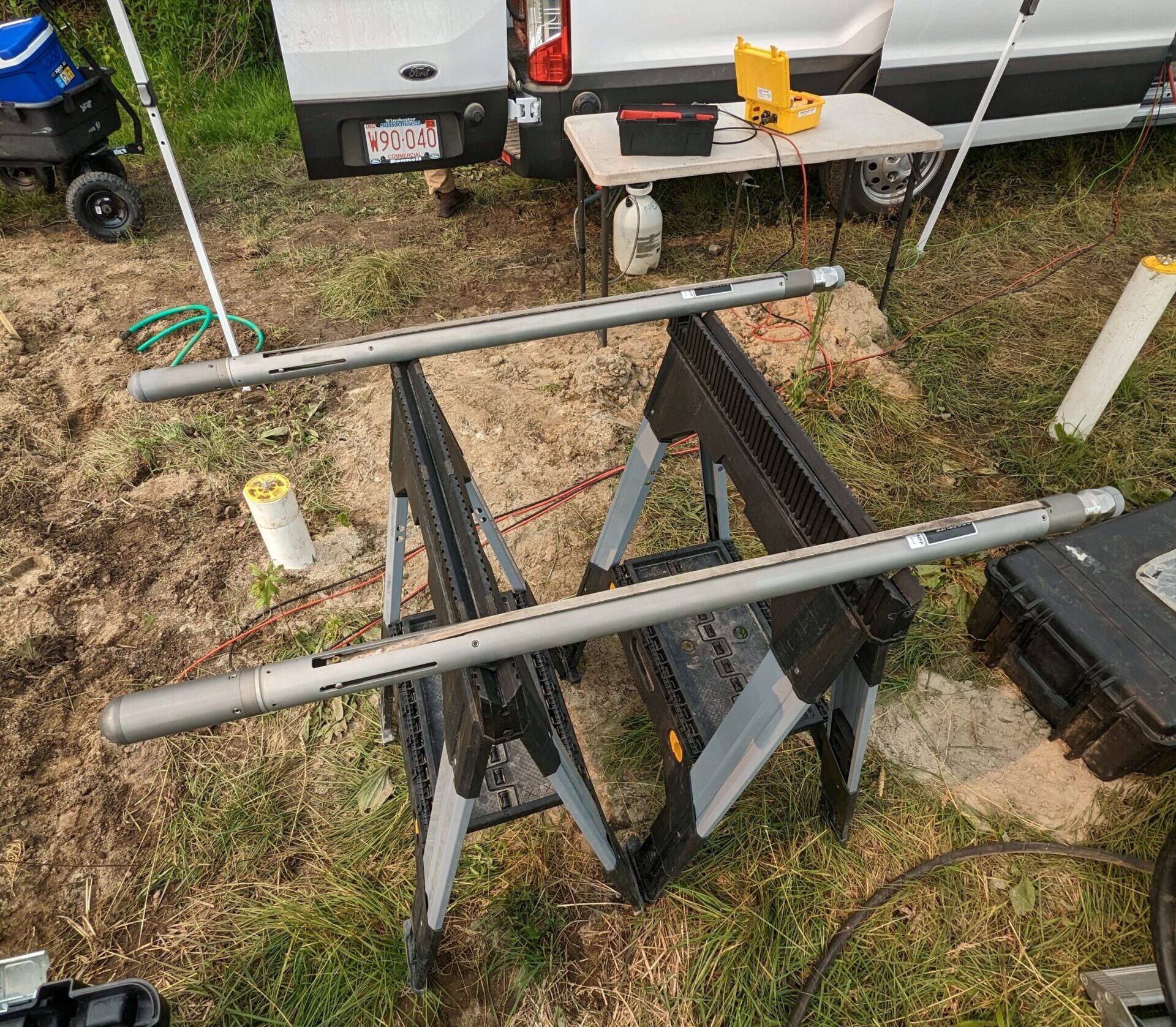
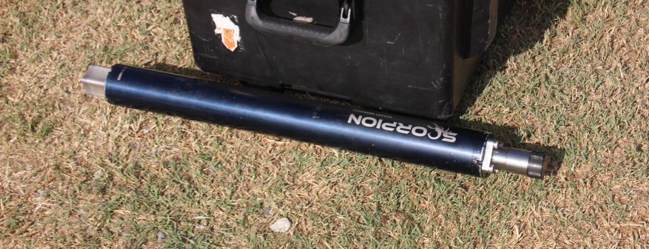
The figures below illustrate a general field setup and equipment for the crosshole seismic test method. Borings are typically spaced 10 to 20 feet apart. Borehole deviation surveys must be conducted to determine accurately the horizontal distance between the borings at depth. Cross-hole testing takes advantage of generating and recording (seismic) body waves, both the P- and S-waves, at selected depth intervals where the source and receiver(s) are maintained at equal elevations for each measurement. Typically, data using source-receiver systems with preferential orientations in tandem (i.e., axial orientations, which complement the generated and received wave type/signal) allows maximum efficiency for measurement of in situ P- or S-wave velocity depending on the axial orientation. Due to the different particle motions along the seismic ray path, it is crucial to use optimal source-receiver systems in order to best record crosshole P- or S-waves. Crosshole testing is three-directional in nature. Therefore, three-component geophones with orthogonal orientations yield optimal results when acquiring crosshole P- and/or S-wave seismic signals. With three-component geophones, there is one vertically oriented geophone and two horizontal geophones. For crosshole tests, one horizontal geophone remains oriented parallel to the axis between the boreholes (radial orientation), and the other one remains oriented perpendicular to the borehole axis (transverse orientation). In this case, the two horizontal axis geophones must remain oriented, radially and transversely, throughout the survey. This is accomplished with magnetometer-based rotating, or with geophones that can be electronically oriented.
Sources for crosshole testing vary from the generation of P-wave seismic energy with specialized sources (e.g., sparkers, airguns, impactors, etc.) to generating shear (S-) wave energy with specialized sources (e.g., horizontal operated solenoids, vertically operated hammers, etc.). These sources vary according to borehole separation and desired signal frequency content; equally, the receivers are designed to match the type of source.
Separation and geometry of multiple pairs of borings dictates the fidelity of the velocity model produced. Thus, it is important to follow the ASTM standards for both borehole completion procedures and borehole deviation measurements to generate the best P- or S-wave velocity profile.
Data Processing
Utilizing digital recording equipment affords the operator the ability to store the data for analysis at a later date; but more importantly, digital data can be filtered, smoothed, and time-shifted during analysis. Also, digital signal processing may be directly performed for coherence, frequency-dependent attenuation, and spectral analysis. Sophisticated processing is rarely required in (engineering) crosshole testing, and the straightforward distance/travel time relationship for velocity computations is considered functional and effective.
Data Interpretation
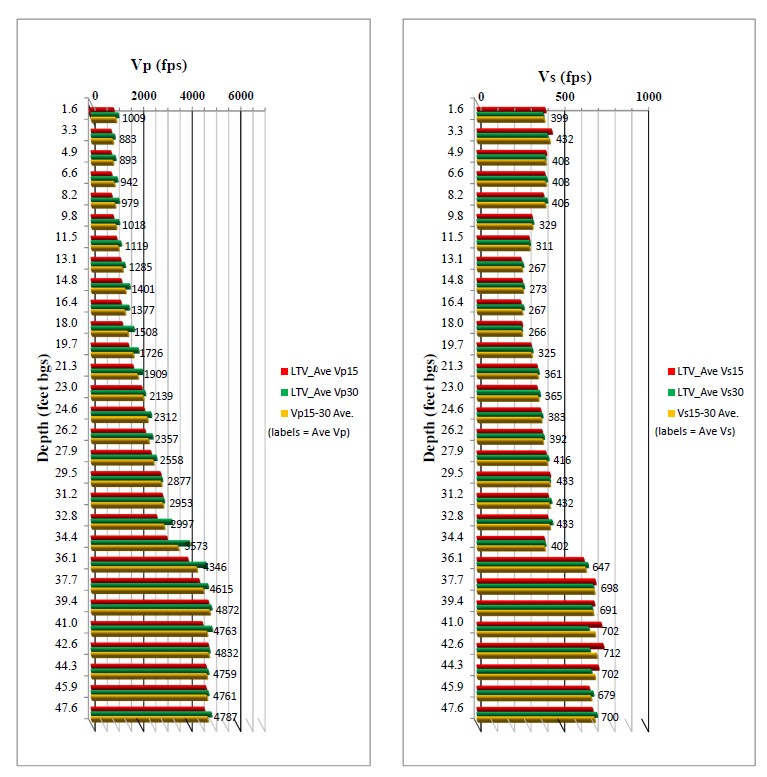
An example of Vp and Vs velocity data is shown below. The Vp and Vs are simply calculated by dividing the borehole distance with the first arrival travel time for the P and S waves. The Vp and Vs shown in this example are calculated from 15-foot and 30-foot borehole intervals. The measured Vp reflects low-density soil to approximately 13 feet below which depth the Vp reflects a gradual increase in saturation of loose organic soil. Vp increases markedly at 35 feet, representing a change to more dense soil. Unaffected by saturation, the Vs profile reveals boundaries of soil stiffness at approximately 9, 20, and 35 feet. The depth intervals between 1.6 to 9 feet and 20 to 35 feet have similar Vs values; whereas the Vs within the 9- and 20-foot interval are very low. The highest Vs below 35 feet represents stiff soil conditions.
Applications

Borehole Logging