Seismic refraction is one of the most commonly used methods to determine thickness of soil and sedimentary layers, and depth to bedrock. The method requires a seismic energy source, usually sledgehammers for depths of 30 m or less, and accelerated weight drops or explosives for larger depths. Both compressional waves (P-waves) and shear waves (S-waves) can be used in the seismic refraction method, although P-waves are most commonly used.
For simple situations with layered geology, the time-distance method using a layered model, or the generalized reciprocal method (GRM) may be sufficient. However, when the geologic formations are irregular or complex, such as in situations with karst features, lenses, channel deposits, or variable bedrock weathering thickness, seismic refraction tomography (SRT) is preferred.
Data Acquisition
The design of a survey for mapping stratigraphy is the same as for any other seismic refraction survey. The length of the geophone spread should be sufficient to image features of interest. Geophone spacing should be based on the resolution needed. Depending on the depth of investigation, an energy source of sufficient size should be considered.
Data Processing
Data processing is the same as for any other seismic refraction survey. Data processing using SRT is often advantageous over other processing methods in situations with complex geology.
Data Interpretation
Seismic refraction data is typically interpreted for depth to and thickness of lithological units, using time-distance curves, GRM or SRT. Correlation with boreholes improves the reliability of the interpretation.
Deliverables
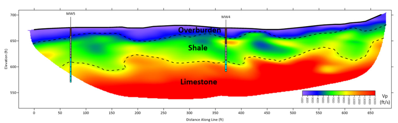
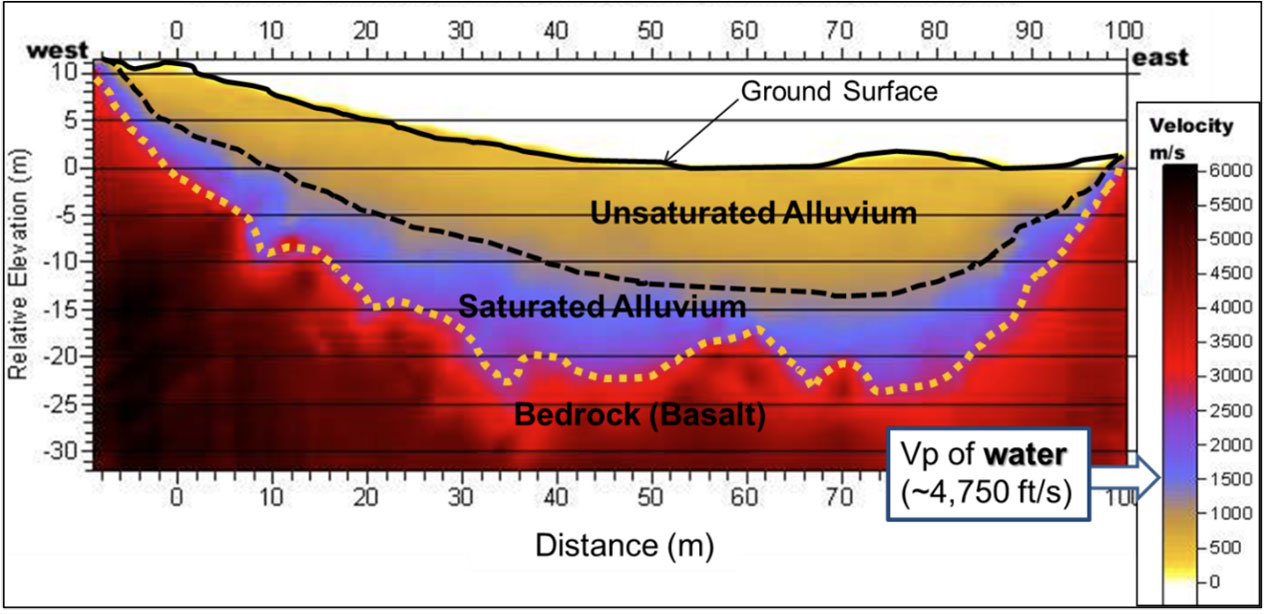
Results of SRT surveys for soil and rock characterization are typically shown as 2D plots of seismic velocity variations. Two examples of 2D SRT profiles with interpretations are shown below.
Advantages
Refraction seismic is generally very effective at characterizing soils and rocks. An important advantage of seismic refraction over other geophysical methods is that seismic velocities are controlled by how rigid a material is. Therefore, in certain situations, seismic refraction can provide information on how the subsurface will actually behave under load, and can provide information on suitable methods for removing the rock, if needed for construction.
Limitations
Probably the most restrictive limitation is that each of the successively deeper layer must have a higher velocity than the shallower layer. This is typically true close to the ground surface where loose soils overlay more compact soils which in turn overlay rock. However, this may not be true in, for instance, sedimentary rock sequences where a compact limestone (with high velocity) may overlay a porous sandstone or shale (with moderate velocity).
Saturated soil can have P-wave velocities approaching those of weathered or fractured bedrock located above the water table. If depth to the water table is unknown, it is possible to interpret the saturated zone as bedrock, which results in a false interpretation of the bedrock depth. In these situations, shear wave refraction seismic may have more accurate results than the more common P-wave surveys, since shear waves are not affected by the water table. To improve reliability it can also be beneficial to combine P-wave SRT with other geophysical methods (such as electrical resistivity imaging) or borings for calibration.
Local noise, for example, traffic, may obscure the refractions from the bedrock. This can be overcome by using larger impact sources or by repeating the impact at a common shot point several times and stacking the received signals. If noise is still a problem, a larger energy source may be required. In addition, since some of the noise travels as airwaves, covering the geophones with sound absorbing material may also help to dampen the received noise.