The seismic refraction method can be used to map the water table surface under certain conditions. A source generates seismic waves that penetrate the overburden and refract along the water table surface. While they are traveling along this surface, they continually refract seismic waves back to the ground surface. These are then detected by geophones placed on the ground surface. Seismic refraction can also detect perched water tables (small pockets of groundwater sitting atop impermeable formations).
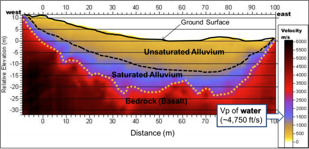
If the water table is located in the overburden, the method works best for coarse-grained sediments with a limited capillary zone where there will usually be a reasonable velocity contrast between the unsaturated sand/gravel, which will have a low velocity (500-800 m/s), and the saturated sand/gravel, which will have a velocity somewhat greater than that of water (1,500-1600 m/s). If sediments are fine-grained, the capillary zone may create a less well-defined seismic velocity contrast between the unsaturated and saturated clay/silt, and the method may underestimate the depth to the water table.
If the water table is close to the bedrock, the water table arrivals may be hard or impossible to detect since bedrock typically has a higher velocity than saturated soils.
Detecting the water table in rocks is typically more difficult than in the overburden without corroborating information. Although the water table may provide an identifiable boundary in a seismic record since the wave velocity increases when pores and fractures become water-filled, there is no specific velocity value associated with the water table in rock. It can therefore be difficult to determine if the increased velocity is due to the presence of a water table or due to increase in rock hardness or quality.
Only compressional waves (P-waves) are used for mapping the water table, since shear waves (S-waves) are not affected by the presence of the water table. For simple situations with layered geology, the time-distance method using a layered model, or the generalized reciprocal method (GRM) may be sufficient. However, when the geologic formations are irregular or complex, or if the water table is expected to vary significantly across the site, seismic refraction tomography (SRT) is preferred.
Data Acquisition
The design of the survey is the same as for any other seismic refraction survey. The length of the geophone spread should be sufficient to image features of interest. Geophone spacing should be based on the resolution needed. Depending on the depth of investigation, an energy source of sufficient size is required. Typically, a hammer is used for depths less than 30 meters and a black powder seismic gun or an accelerated weight drop for depths over 30 meters.
Data Processing
Data processing is the same as for any other seismic refraction survey. Data processing using SRT is often advantageous over other processing methods in situations with complex geology.
Data Interpretation
Seismic refraction data is typically interpreted for depth to the water table, using time-distance curves, GRM or SRT. If the water table is located in the overburden, the seismic velocity of water (approximately 1,500 m/s) can be used to make an initial interpretation of depth to the water table. Correlation with water or monitoring wells improves the reliability of the interpretation.
Deliverables
Results of SRT surveys for stratigraphy mapping are typically shown as 2D plots of seismic velocity variations. An example of a 2D SRT profile is shown below.
Advantages
Seismic refraction is generally very effective at mapping the groundwater table, especially when located in the overburden, and in coarse–grained formations. An important advantage is that the seismic velocity of saturated sand/gravel is typically very close to that of water (approximately 1,500 m/s), which improves the confidence in the interpretation.
Limitations
In fine-grained sediments, the capillary zone may create a poorly defined seismic velocity contrast between the unsaturated and saturated clay/silt, and the seismic refraction method may underestimate the depth to the water table.
Water tables in rock may provide an identifiable boundary in a seismic record, but there is no specific velocity value associated with it. It can therefore be difficult to determine if the increased velocity is due to the presence of a water table or due to increase in rock hardness or quality. Perched water tables may also be misinterpreted as a true water table surface.
Probably the most restrictive limitation of seismic refraction in general is that each of the successively deeper layers must have a higher velocity than the shallower layer. This is typically true close to the ground surface where loose soils overlay more compact and perhaps saturated soils which in turn overlay rock. However, this may not be true in, for instance, sedimentary rock sequences where a compact limestone (with high velocity) may overlay a porous sandstone or shale (with moderate velocity).
Local noise, for example, traffic, may obscure the seismic refractions. This can be overcome by using larger impact sources or by repeating the impact at a common shot point several times and stacking the received signals. If noise is still a problem, a larger energy source may be required. In addition, since some of the noise travels as airwaves, covering the geophones with sound absorbing material may also help to dampen the received noise.